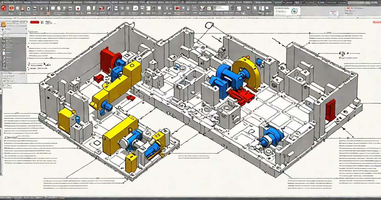
SolidWorks MBD (Model-Based Definition) embeds all necessary engineering data-dimensions, tolerances, notes, material specs, and manufacturing instructions-directly into a 3D CAD model, replacing traditional 2D engineering drawings as the primary source of manufacturing information.
MBD transforms how product data is communicated across design, manufacturing, and quality teams. Instead of referencing a separate 2D drawing, engineers and machinists access everything needed from the 3D model itself. This reduces misinterpretation, speeds up production cycles, and aligns with modern digital manufacturing practices.
According to the American Society of Mechanical Engineers (ASME), model-based definition supports consistent interpretation of design intent across global supply chains. The ASME Y14.41 standard formalizes MBD practices, ensuring that 3D models meet technical communication requirements equivalent to 2D drawings.
In SolidWorks, MBD uses annotated 3D geometry to convey manufacturing and inspection requirements. Dimensions, geometric tolerances (GD&T), surface finishes, and assembly instructions appear as intelligent annotations tied directly to model features-not as overlay graphics on a flat sheet.
When a model is exported as a STEP AP242 file, all MBD data-including tolerance zones, datums, and feature control frames-is preserved. This enables downstream systems like CNC machines, inspection software, and PLM platforms to interpret the model without relying on external documents.
For example, a machined bracket with a hole requiring ±0.05 mm tolerance and a surface finish of 32 µin Ra would have those specifications applied as embedded annotations in the 3D model. A CAM system reading the model automatically applies the correct toolpath and feed rate based on the defined parameters.
MBD integrates several elements into a single digital artifact:
These elements are managed through SolidWorks' annotation tools and can be controlled via custom templates. Teams can enforce company-wide standards by setting default styles for tolerances, fonts, and placement rules.
Organizations adopt different levels of MBD maturity depending on their processes and industry requirements:
| Level | Description | Use Case |
|---|---|---|
| Basic MBD | Dimensions and tolerances added to 3D model; no formal export format. | Internal design reviews, prototype validation. |
| Standard MBD | Full GD&T, annotations, and export in ISO 10303-242 (STEP AP242). | Manufacturing handoff, supplier collaboration. |
| Advanced MBD | Integrated with PLM, CAM, and inspection systems; supports automated verification. | High-volume production, aerospace, medical devices. |
Advanced MBD requires alignment with enterprise systems. For instance, a manufacturer producing automotive sensors may use MBD data to drive automatic inspection routines in a coordinate measuring machine (CMM), reducing manual setup time by 60% compared to drawing-based workflows.
Many assume MBD eliminates the need for documentation entirely. That's incorrect. MBD replaces 2D drawings as the primary source of truth, but supplementary documentation-such as test procedures, safety manuals, or compliance certificates-still exists separately.
Another misconception is that MBD only benefits large manufacturers. In reality, small shops using CNC routers or 3D printers benefit from MBD too. A maker building custom prosthetics reported a 40% reduction in rework after switching from 2D drawings to MBD, due to clearer tolerance definitions and fewer misinterpretations during machining.
A lesser-known fact: MBD annotations are not just visual-they're searchable and queryable. Using SolidWorks' API, developers can extract all tolerances on a specific face and generate reports for quality assurance. This capability is often overlooked in early MBD adoption.
A company designing a titanium spinal implant used SolidWorks MBD to define critical dimensions and surface finishes. The model included:
The model was exported as a STEP AP242 file and sent to a contract manufacturer. The CNC programming software read the embedded tolerances and generated toolpaths accordingly. During inspection, the CMM program referenced the model's GD&T directly, reducing setup time from 45 minutes to under 10 minutes.
This workflow cut the time from design release to first production part from 14 days to 6 days, according to internal project logs.
While both serve the same purpose-communicating design intent-the methods differ fundamentally:
| Aspect | Traditional 2D Drawing | SolidWorks MBD |
|---|---|---|
| Data Location | Separate document, often PDF or DWG | Embedded in 3D model |
| Interpretation Risk | Higher-misalignment between views common | Lower-annotations tied to actual geometry |
| Update Workflow | Manual revision tracking required | Version-controlled within PDM |
| Downstream Use | Requires conversion to CNC formats | Direct integration with CAM and inspection tools |
Start with a pilot project on a component with high manufacturing complexity. Use standardized templates for annotations to ensure consistency. Train all stakeholders-designers, manufacturing leads, and quality inspectors-on interpreting MBD data.
Validate your MBD model against the ASME Y14.41 standard. SolidWorks includes a Model-Based Definition Checker that flags missing tolerances, invalid symbol usage, or inconsistent units. Run this tool before exporting to avoid errors in downstream processes.
I once reviewed a model where a critical diameter was labeled as "0.5" without units. The checker flagged it as ambiguous. After adding "mm," the issue resolved. Small oversights like this cause costly errors when ignored.
SolidWorks MBD is a structured method for embedding engineering data directly into 3D models, replacing reliance on 2D drawings. It improves clarity, reduces errors, and accelerates product development. As manufacturing becomes increasingly digital, MBD is no longer optional-it's essential for competitive, high-quality production.